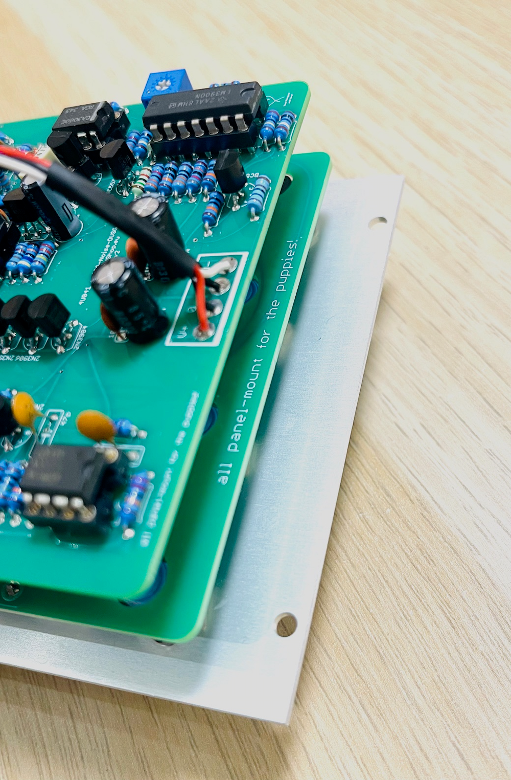
4U041 - SSG/Noise/DUSG
4U041 - SSG/Noise/DUSG
Couldn't load pickup availability
4U041 - SSG/Noise/DUSG
This module is a combination of two well know and super complex/flexible modules - the Smooth And Stepped Generator and the Dual Universal Slope Generator, with the Noise module, as added bonus.
Together, these three forms one of the most complex (and dense) module.
SSG (from the CGS archives)
The Smooth & Stepped Function Generator (SSG) is s a complex multi-functional module to provide various slew and sample functions.
The Smooth section will place a positive and negative slew (glide) on a changing input voltage for lag effects, voltage controlled portamento, and non-linear, low frequency filtering. With the CYCLE jack patched to the input, the Unit will oscillate yielding a voltage controlled triangle wave LFO. A high level into the HOLD input will hold the current output level, whether the unit is oscillating or processing an external control voltage. This is identical to a track-and-hold function.
The Stepped function can be used as a sample-and-hold with voltage controlled slew rate limiting. Slew rate limiting limits the size of the step at the output. With the step size limited to a small value, if the input is a random voltage, the output is a random voltage also, but it will only vary slightly from step to step, gradually covering the entire range of the input random voltage. No large changes in the output will be allowed. With the Cycle jack patched to the input and a trigger applied to the Sample input, complex staircase waveforms are generated.
The coupler is an internal comparator comparing the Smooth and the Stepped outputs. This is useful for generating complex control voltages and for patching a random voltage generator.
Noise (from the CGS archives)
In it's simplest form, it contains three basic outputs, White noise, Pink noise, a random voltage suitable for use with Sample and Hold modules and a Sample and Hold circuit, which is either clocked by the Smooth Cycle output or by an external clock.
DUSG (from the CGS archives)
The slopes from the DSG are linear (equal voltages per unit of time), but they can be altered using feedback. If the OUTPUT is patched to the VC IN jack, then the slope can be given an exponential or a logarithmic shape determined by the amount of feedback set by the processing knob. Since both the RISE and FALL can be switched to be controlled separately or together, the slope of either or both can be shaped using this technique. This is useful for producing slow, gradual amplitude changes with the Equal Power VCA modules.
If the TRIG IN jack is connected to the TRIG OUT jack, the DSG will oscillate with a waveform and frequency set by the RISE and FALL knobs. A series of pulses will appear at the TRIG OUT jack, and the duty cycle (the time the pulse is high compared to when it is low in each cycle) is set by the RISE and FALL knobs. The FALL knob determine how long the pulse is low. When the DSG is in the RISE part of the cycle or when the output is zero or less, the output of the TRIG OUT will be high. In some applications, a pulse with a very long duty cycle will cause erratic triggering in other modules. If such a symptom occurs, try increasing the FALL time and decreasing the RISE time to get the same pulse rate.
The DSG may be used as a positive peak follower by setting the RISE time to minimum (full CW) and applying an audio signal to the IN jack. Adjust the FALL knob for a compromise between response time and the best filtering of the audio component at the DSG output. If the FALL time is turned to minimum, and the RISE knob adjusted for optimum response time and filtering, then the unit will function as an envelope, follower-producing a negative envelope corresponding to the negative peaks of the input audio signal.
Adjustments on the DSG board are set to obtain a 0 to +5 volt level when the unit is cycling, producing a 100Hz triangle wave. An oscilloscope is required for this adjustment. This should not need to be adjusted unless components are replaced.
PCBs:
1.6 mm thick, double sided, green
base material FR4-Standard TG 135-140
surface finish HASL
part values are silkscreened
all panel mount!
Front panel
1.6 mm, PCB material with colour front print that "mimics aluminium"
4" x 175 mm
mounting holes - 3.5 mm, follows the LW specification (top and bottom)
please note, minor imperfection may occur
no parts, just the PCB and panel
Share